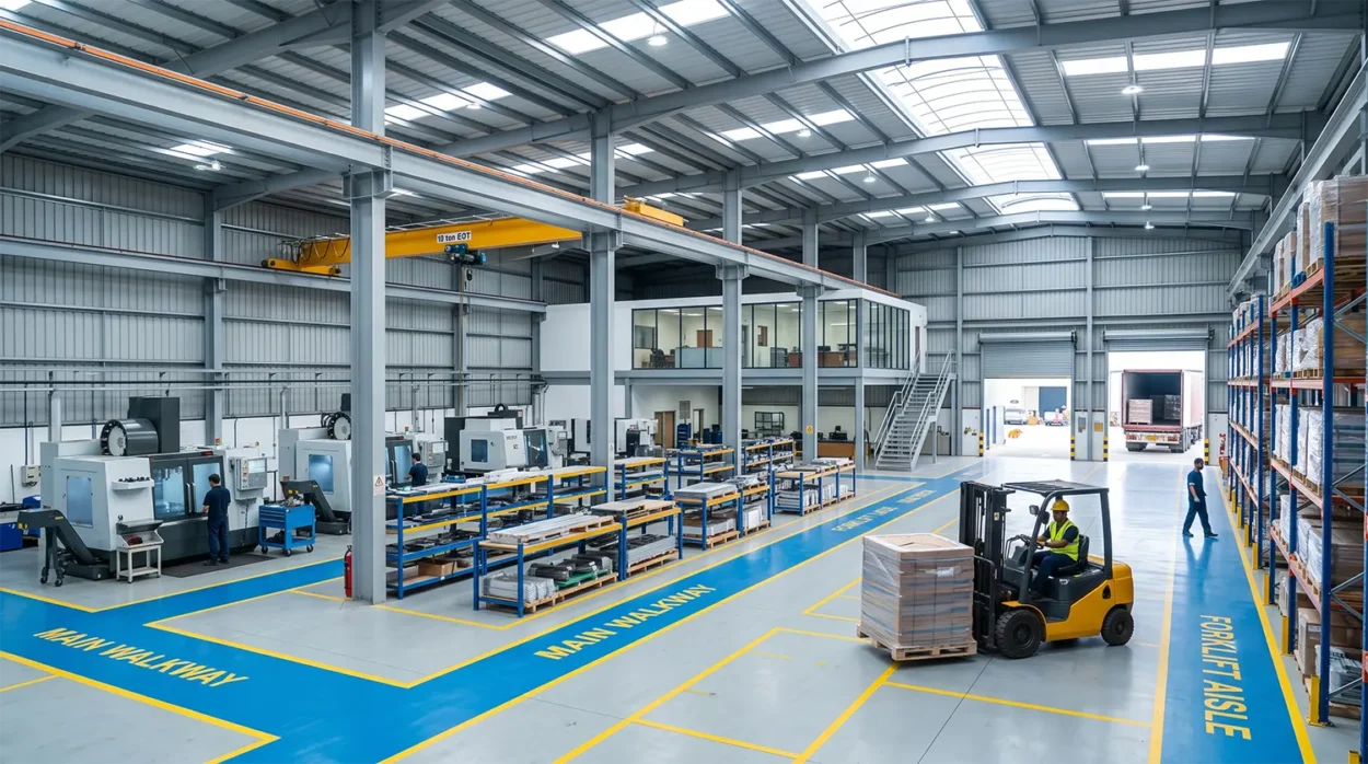
Most factory projects go wrong long before the first anchor bolt is cast. A plot is bought, a shed size is fixed from a rough guess, and only then does anyone check whether the machines, the crane and the material flow actually fit inside it. Good PEB factory design runs the other way. Production comes first, the building follows.
This guide walks through how clear height, span, bay spacing, crane provisions and machine layout are decided, and how those decisions ripple through structure, usable floor area and your ability to expand later.
Key Takeaways
- Machine dimensions, handling method and material flow should be frozen before any structural drawing is started.
- Clear height is set by the tallest operation plus service and handling clearances – not by a standard shed height.
- Wider spans free the floor but add steel weight; bay spacing should align with machine lines and loading positions.
- Crane provisions, mezzanines and future bays are cheap to design in and expensive to retrofit.
- Final spans, heights, loads and foundations must come from a qualified structural engineer for your site.
Should Production Drive the Building, or the Other Way Round?
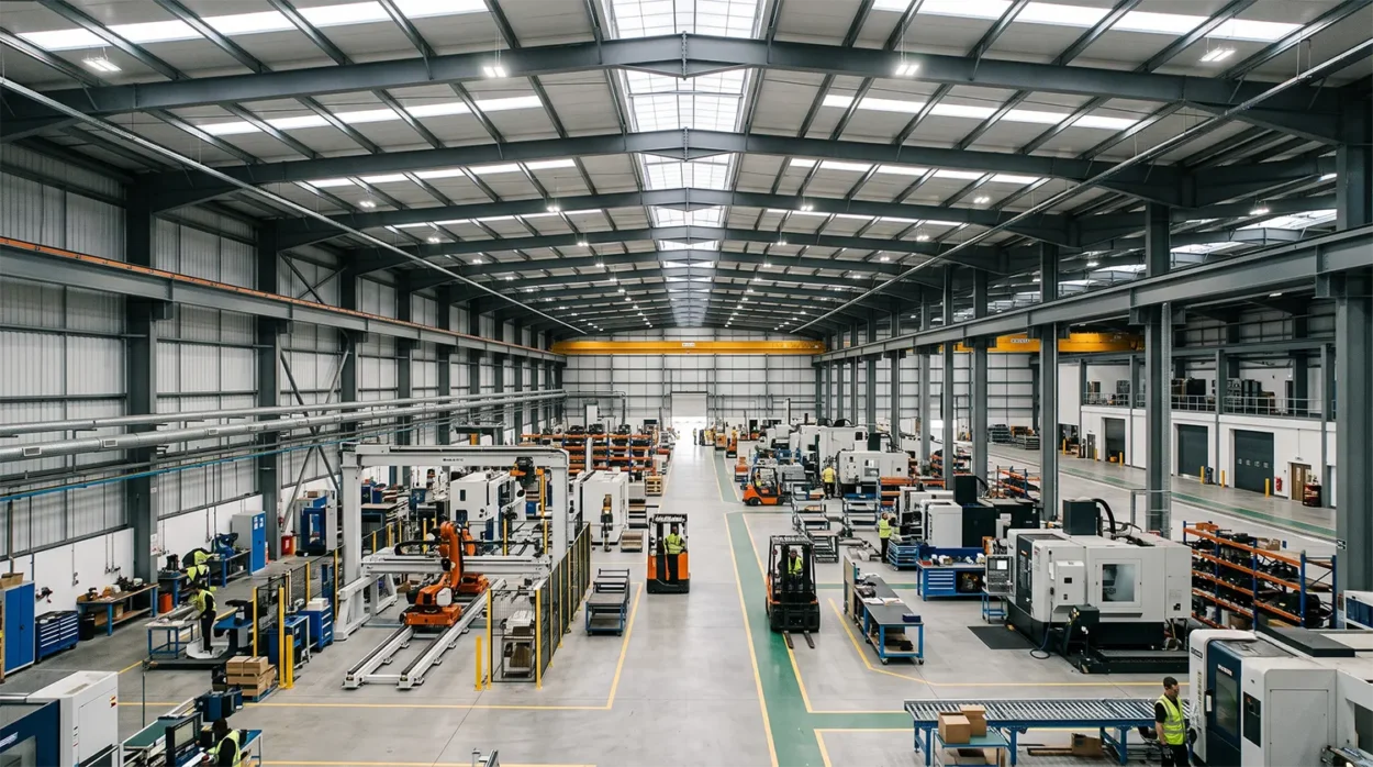
Production drives it. In a well-planned manufacturing facility, the building is the last variable, not the first.
The sequence is:
process flow → equipment list → handling method → space envelope → structural design.
That matters because a pre-engineered factory building is engineered to order. Every frame is sized for the loads and geometry you specify. If the machine list changes after fabrication starts, you’re paying for redesign, not adjustment.
Start by documenting your process as a flow, station by station: where raw material enters, what happens at each stage, where work-in-progress waits, and where finished goods leave. Then list every machine with its footprint, working envelope, foundation requirement, utility connections and maintenance clearance. Equipment suppliers publish these in their installation manuals. Use their figures, not estimates.
A pattern we see often: clients arrive with a plot size and a budget, but no machine layout. The first meeting that actually saves money is the one where the equipment drawings come out. Metal Tree’s engineering team works from this input set when developing industrial PEB building designs, because the same plot can yield very different usable areas depending on how the frames are arranged.
How Do You Fix Clear Height in Factory Shed Design?

Clear height is the vertical distance available for work – typically measured to the underside of the rafter or to the crane hook level, depending on what governs.
Build it up in layers rather than picking a round number:
- Tallest machine height, including any raised platform or foundation pedestal
- Working clearance above the machine for tool changes, charging, loading hoppers or die removal
- Handling clearance – the lift height your hoist, stacker or forklift mast needs at full extension
- Services zone for ducting, fire lines, cable trays, lighting and exhaust
- Structural depth of the rafter itself, which eats into the space at mid-span
Storage height is a separate check. If finished goods are racked or palletised several levels high, the racking layout may govern clear height rather than any machine.
Height is not free. Taller columns mean higher wind loads, heavier bracing and more cladding area. That said, adding height at the design stage costs far less than raising a roof later. Resolve it once, properly.
How Should Span and Bay Spacing Follow Machine Layout?
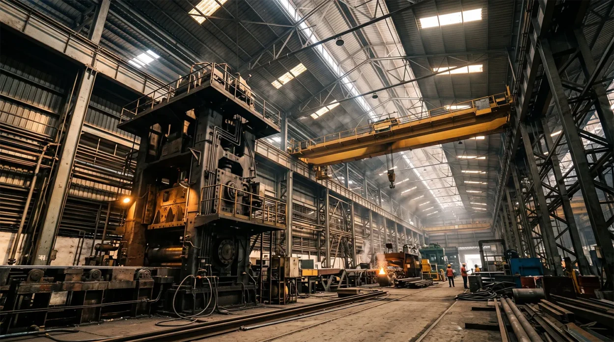
Span is the clear width between column lines. Bay spacing is the distance between frames along the building length. Together they decide how much of your floor is genuinely usable.
Clear span gives a column-free floor. That suits flexible layouts, wide machines, cross-traffic and anything you expect to rearrange. The trade-off is steel weight – deeper rafters and heavier frames as the span grows.
Multi-span introduces interior columns and reduces steel, but those columns must land where they don’t block a machine, an aisle or a crane path. A column in the middle of a production line can quietly cost you more in lost throughput than it saved in tonnage.
The practical method: draw the machine layout at scale first, mark every aisle and maintenance zone, then see where column lines can sit without interference. Bay spacing should line up with the rhythm of your operation – machine pitch, loading dock positions, mezzanine edges.
A useful discipline in factory building design is to test two or three span-and-bay combinations against the same layout and compare usable area, not just tonnage. The cheapest structure and the best factory are rarely the same drawing. Your actual span limits, frame depths and bracing will be determined by structural analysis against applicable Indian standards – IS 800 for steel design, IS 875 for loads, and the National Building Code – using your site’s wind and seismic data.
Where Do Crane Requirements Change the Structure?
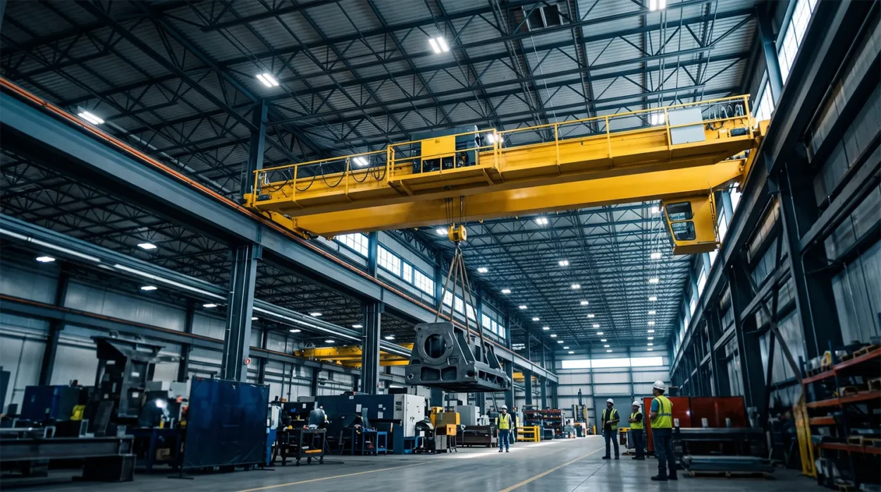
Cranes change almost everything. An EOT or under-slung crane transfers moving vertical, lateral and longitudinal forces into the columns, which affects column sections, bracing, gantry girders and foundations.
You need to confirm, from the crane supplier: capacity, span, hook approach, duty class, wheel loads and required hook height. These figures are project-specific and come from the crane manufacturer’s data sheet – never assume them.
Even if a crane isn’t in the first phase, say so early. Designing columns and foundations to accept a future crane is a modest addition now. Strengthening an erected frame later means shutdown, re-analysis and retrofit work. The same applies to jib cranes, monorails and heavy roof-hung equipment. Metal Tree’s pre-engineered building solutions routinely include crane-ready framing and mezzanine provisions specified at the design stage for exactly this reason.
Planning Material Flow, Storage, Loading and Maintenance Access
Floor space is consumed by three things: machines, material and movement. Layouts usually fail on the third.
Material flow should be single-directional where possible – in at one end, out at the other, or a U-shape returning to a shared dock. Backtracking wastes handling time and creates congestion.
Raw material storage needs to sit near the entry point and near the first operation, sized for your reorder cycle rather than a nominal corner.
Finished goods need an accumulation area before dispatch, plus the turning circle your forklifts or trailers actually require.
Loading zones deserve specific attention: vehicle type, dock height versus ground-level loading, canopy or bay extension, queuing space outside, and approach geometry within the plot.
Maintenance access is the one most often forgotten. Every machine needs a pull-out zone for its longest component, plus space for a technician and their tools. Panel boards, compressors and pumps need standing clearance in front.Worker movement should be planned as marked walkways separated from vehicle paths, with safe crossing points and clear routes to exits.
Ventilation, Lighting, Utilities, Offices and Mezzanines
Envelope decisions affect running cost for the life of the plant.
Ventilation in a factory shed design usually combines ridge ventilators, turbo ventilators or louvres with wall openings for cross-flow. Process heat, fumes and welding smoke may require local extraction designed separately.
Natural lighting through polycarbonate roof sheets and wall lights reduces daytime electricity use. Place them to avoid glare at inspection stations and screens.
Utility areas – compressor room, DG set, panel room, water treatment, scrap yard – should be positioned outside the main production envelope where possible, with routing planned so pipes and cables don’t cross aisles.
Office spaces work well as a prefabricated block or modular site office attached to the shed, keeping administrative movement out of the production floor.
Mezzanine floors recover area for stores, QC labs, offices or sub-assembly. The floor load, staircase position and edge geometry must be declared upfront, since mezzanines change column loads and foundations. Future expansion is planned by orienting the building so one gable end is free, keeping that end’s cladding removable, and sizing the end frame accordingly. Insulated envelope options such as PUF sandwich panels can be extended in the same system.
A Step-by-Step PEB Factory Design Framework
- Define production targets – output volume, shifts, product mix, growth horizon.
- Map the process flow – every stage, in sequence, with WIP buffers.
- Compile the equipment schedule – footprints, weights, utilities, foundations, maintenance clearances, from supplier data.
- Fix the handling method – forklift, crane, conveyor, manual. This sets aisles and heights.
- Draft the machine layout at scale, including walkways, storage and dispatch.
- Derive the building envelope – clear height, span options, bay spacing, dock positions.
- Add supporting spaces – mezzanine, offices, utility rooms, welfare areas.
- Hand over to structural engineering for load analysis, frame design and foundations against site-specific wind, seismic and soil data.
- Lock the design before fabrication. Late changes are the single biggest cost driver.
Common Factory Design Mistakes
- Fixing shed dimensions before finalising the machine list
- Under-sizing clear height and discovering the hoist won’t clear the machine
- Placing interior columns without checking them against the layout
- Ignoring maintenance pull-out space until a breakdown forces the issue
- No crane provision in a plant that will obviously need one within three years
- Aisles sized for an empty forklift rather than a loaded one
- Treating ventilation and lighting as an afterthought
- Building right up to the plot boundary on all four sides, leaving nowhere to expand
Practical Design Checklist
- Process flow diagram approved
- Equipment schedule with supplier drawings
- Handling method and lift heights confirmed
- Crane data sheet obtained (or future provision declared)
- Scaled machine layout with aisles and maintenance zones
- Clear height built up layer by layer
- Span and bay options compared on usable area
- Raw material and finished goods areas sized
- Loading zones checked against vehicle geometry
- Mezzanine loads and staircase positions declared
- Ventilation, lighting and utility routing planned
- Expansion direction kept clear
- Soil investigation report available
- Structural design by a qualified engineer
Frequently Asked Questions
There’s no standard answer. It’s derived from your tallest machine, the clearance needed above it, hoist or forklift lift height, the services zone and rafter depth. Storage racking may govern instead. Your engineer confirms the final figure.
Not always. Clear span gives column-free flexibility but uses more steel. Multi-span is lighter where interior columns can sit outside machine and aisle zones. Compare both against your actual layout.
Sometimes, but it requires re-analysis of columns, bracing and foundations, and often physical strengthening. Declaring a future crane during design is far simpler and cheaper.
By aligning frame positions with machine pitch, aisles, dock locations and mezzanine edges, then optimising for steel economy within those constraints.
Yes. A pre-engineered factory building extends readily along its length if the end frame is designed for it and the expansion side is kept clear.
Planning Your Facility
Get the production requirements right and the building design follows logically. Get them wrong and you’ll be working around the mistake for twenty years. If you’re at the planning stage, bring your process flow and equipment list to the conversation early. Metal Tree’s team can develop layout options, envelope alternatives and crane-ready framing before anything is committed to fabrication.
Talk to Metal Tree about your factory project →Structural spans, member sizes, crane capacities, load values and foundation details in any project must be established by a qualified structural engineer using site-specific data and the applicable Indian standards. This article is a planning guide, not a design document.